CUSTOM-ENGINEERED FOR UKRAINE INTEGRATOR:
FULL-SPECTRUM DRONE DEFENSE AMPLIFICATION SOLUTION
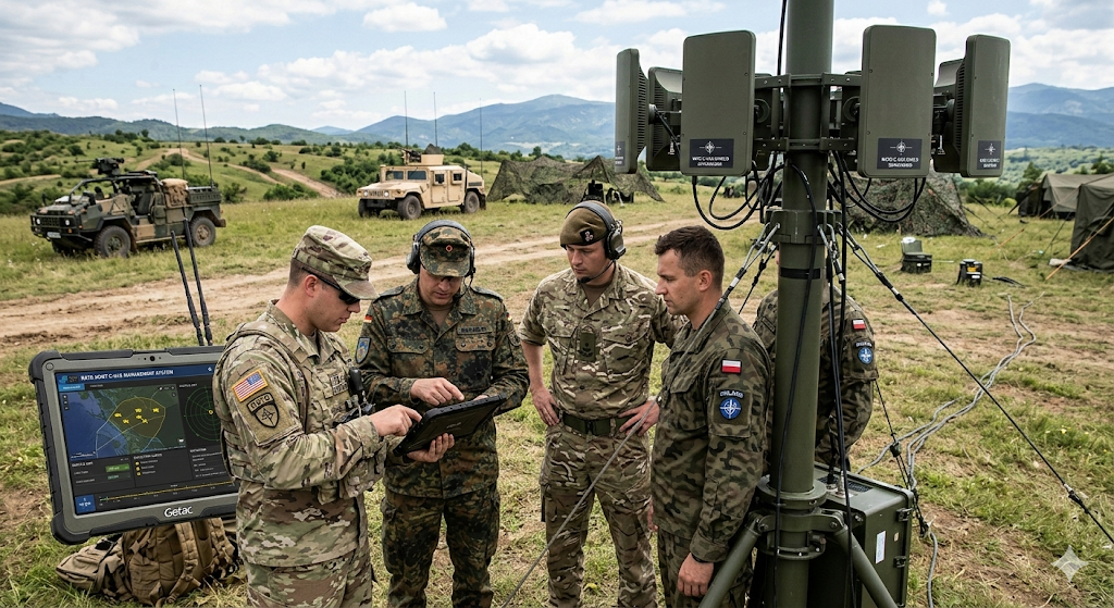
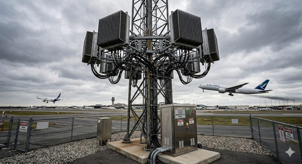
Delivering mission-critical RF power modules with ultra-wideband coverage, enabling seamless integration into next-generation counter-UAS systems deployed across Eastern European defense networks.
Mission Parameters at a Glance
Ukraine Border Zone
Integrator
Jamming Gap
Design to Batch
Similar operational requirements? Let's discuss your specific integration needs.
Request Project ConsultationThe Ultimate Counter-UAV Arsenal
Cognitive SDR precision combined with overwhelming RF power. A complete, scalable hardware ecosystem designed to neutralize modern frequency-hopping threats.
Smart Digital RF Source
Moving beyond brute-force noise. Our Software-Defined Radio (SDR) serves as the intelligent core, generating precisely tailored digital interference codes to sever specific C2 links.
-
100MHz-6000MHz Dominance Seamless frequency coverage. Up to 100MHz real-time bandwidth per channel, combining for a massive 200MHz sweep.
-
Protocol-Specific Defeat Built-in digital modulation to instantly neutralize ELRS, TBS Crossfire, Flysky, Ocusync, and Lightbridge protocols.
-
GNSS Navigation Denial Dedicated 'GNSS_70M' disruption codes to immediately disable hostile GPS, GLONASS, and BeiDou navigation systems.
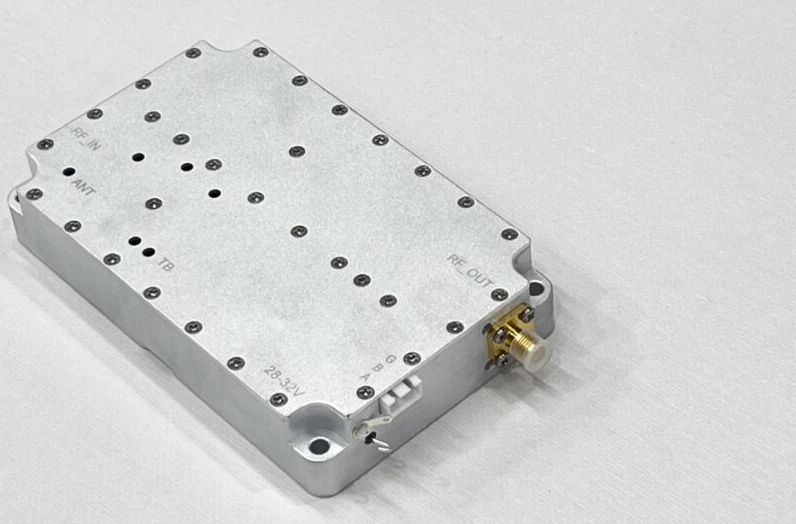
Ultra-Broadband Amplification
A smart signal requires raw physical power to create an impenetrable dead-zone. Seamlessly integrate the SDR with our ruggedized, high-efficiency PA modules to scale your defense.
-
1W to 1000W Scalability Choose the exact ERP required for your mission. Engineered for high stability under continuous tactical operation.
-
Targeted Band Configurations Available wideband amplifier arrays are built for the following spectrum ranges: 30–512 MHz, 300–1700 MHz, 300–2700 MHz, and 2000–6000 MHz. Customization is available from 20 MHz to 20 GHz, specifically tailored for ultra-wideband applications.
-
Clean Signal Output Exceptional out-of-band rejection (>40 dB) ensures you only jam the intended targets without self-interference.

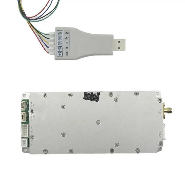
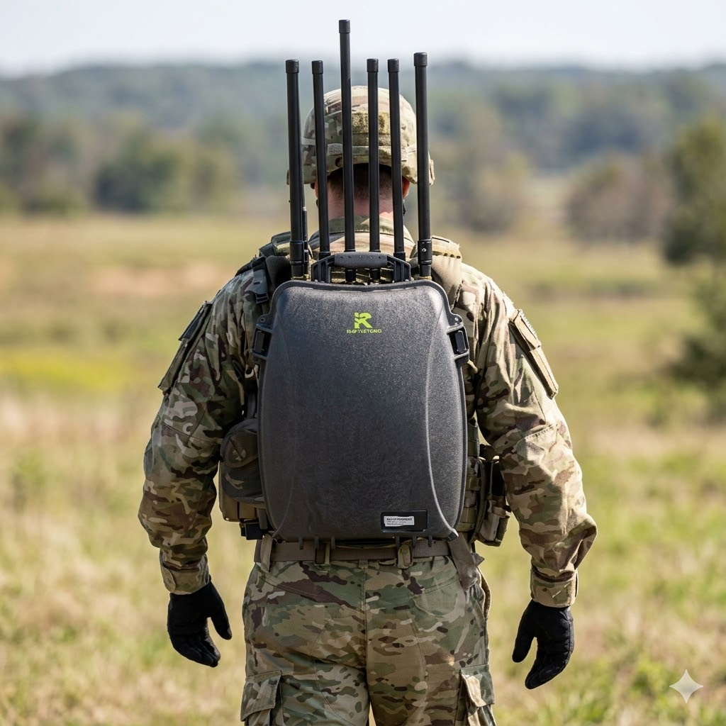
Tactical Hardware Integration
Compact, dual-channel, and plug-and-play. Engineered for rapid deployment in man-portable, vehicle-mounted, or fixed-site C-UAS arrays.
-
True Dual-Channel Execution Independent outputs. Deploy an LFM sweep on 900MHz (CH1) while simultaneously blasting OFDM on 5.8GHz (CH2).
-
Ultra-Compact Form Factor The SDR module measures just 60×140×14mm (<200g), offering a minimal footprint for complex system integrations.
-
RS422 Real-Time Control Included SDR config software allows instant switching of frequency, gain, and targeted interference codes.
The Strategic Challenge Breakdown
Our client faced a triple threat: technical complexity, environmental extremes, and supply chain reliability issues that traditional vendors couldn't solve.
Integrating amplifiers from multiple suppliers created cascading impedance mismatches and inter-module interference, resulting in up to 40% power loss.
- Inconsistent 50Ω impedance matching between vendors
- Harmonic interference degrading output purity
- Thermal runaway from inefficient power transfer
Field deployment conditions ranging from -40°C winter operations to +85°C vehicle-mounted scenarios caused critical frequency drift in standard components.
- Center frequency shift exceeding ±5MHz at extremes
- Gain variation of ±3dB compromising coverage
- Component failure from thermal cycling stress
Previous suppliers secretly replaced specified components with cheaper alternatives, causing catastrophic field failures and contract penalties.
- GaN transistors swapped with inferior LDMOS parts
- Refurbished capacitors causing premature failure
- No traceability documentation for QA audits
Have you experienced similar integration challenges? Our engineering team can provide targeted solutions.
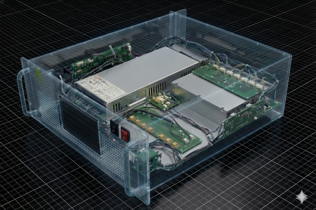
Speak With RF EngineersThe "Lego" Solution Architecture
We designed a modular ecosystem where every component connects seamlessly—eliminating compatibility headaches and allowing rapid system customization for evolving mission requirements.
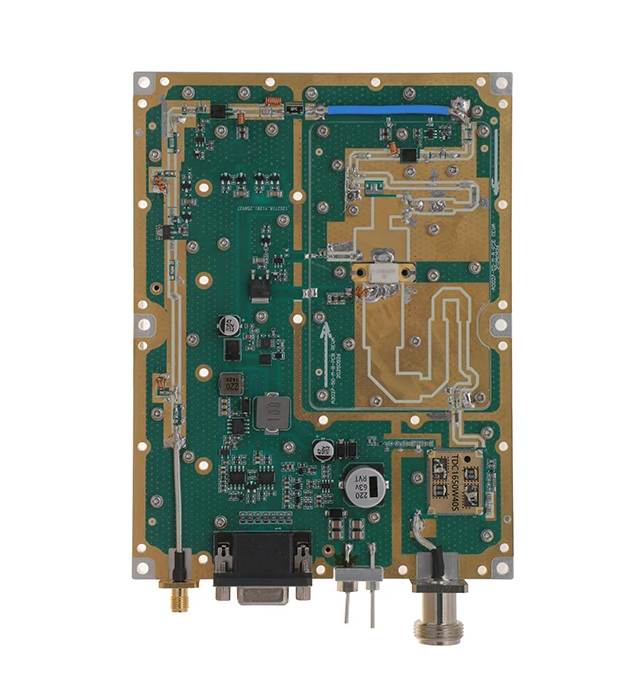
Wideband Core Module
Antenna Interface
Pre-matched N-type and SMA connectors optimized for directional, omnidirectional, and phased array antenna systems.
VCO/DDS Source
Voltage-controlled and direct digital synthesis signal generators with phase-locked loop stability for precise frequency targeting.
SDR Platform
Software-defined radio integration enabling real-time waveform adaptation and cognitive jamming capabilities.
Power Management
Intelligent power distribution with overcurrent protection, thermal monitoring, and battery management system compatibility.
Plug-and-Play Integration
Standardized interfaces mean your team spends less time on hardware debugging and more time on mission-critical development.
Future-Proof Scalability
Modular architecture allows field upgrades and frequency band additions without complete system redesign or requalification.
Single-Source Accountability
One engineering team, one bill of materials, one point of contact—eliminating vendor finger-pointing when issues arise.
Ready to simplify your RF integration architecture? Request our modular solution catalog.
Download Integration GuideTechnical Deep Dive: Full System Specs
Our complete hardware ecosystem. Scroll through the comprehensive parameter matrix of our GaN Power Amplifiers and SDR Digital Sources.


Ultra-Broadband PA Series
Complete GaN Amplifier Array & SDR Controller
| Frequency Band | Output Power (Psat) | Gain (dB) | VSWR |
|---|---|---|---|
| V/UHF Band Modules | |||
| 30 - 512 MHz | 30W / 50W / 100W | 36 - 51 dB | < 1.8 |
| 30 - 512 MHz | 150W / 200W | 43 - 54 dB | < 1.8 |
| L-Band & S-Band Modules | |||
| 300 - 1200 MHz | 30W / 50W / 100W | 36 - 51 dB | < 1.8 |
| 300 - 1200 MHz | 150W / 200W | 43 - 54 dB | < 1.8 |
| 300 - 1700 MHz | 30W / 50W / 100W | 36 - 51 dB | < 1.8 |
| 300 - 1700 MHz | 150W / 200W | 43 - 54 dB | < 1.8 |
| 300 - 2700 MHz | 30W / 50W / 100W | 36 - 51 dB | < 1.8 |
| 300 - 2700 MHz | 150W / 200W | 43 - 54 dB | < 1.8 |
| C-Band & High Frequency Modules | |||
| 2000 - 6000 MHz | 30W / 50W / 100W | 36 - 58 dB | < 1.8 |
| 2000 - 6000 MHz | 150W / 200W | 43 - 58 dB | < 1.8 |
| 6000 - 8000 MHz | 50W / 100W / 200W | 47 - 53 dB | < 2.0 |
| Parameter | Value | Notes |
|---|---|---|
| Technology | 3rd Gen GaN Transistors | Highest power density |
| Operating Voltage | 24V - 32V DC | 28V Nominal |
| Instant Bandwidth | Up to 200 MHz | Broadband/OFDM Ready |
| Spurious Rejection | < -60 dBc | Clean signal output |
| PA Enable/Disable | ≤ 10 μs | 0/3.3V Logic Levels |
| Integrated Protection Suite | ||
| Over Temperature | Auto-Shutdown > 80℃ | Auto-recovery < 70℃ |
| VSWR Protection | Open/Short Shutdown | Latched fault, external reset |
| Over Voltage / Current | Auto-Shutdown | Limits vary by power rating |
| Alarm Indicator | TTL Low/High | PIN output status |
| Parameter | Specification | Notes |
|---|---|---|
| Environment Cert | MIL-STD-810F | Vibration / Shock / Altitude |
| Operating Temp | -40℃ to +60℃ | Storage: -55℃ to +85℃ |
| Cooling | External Heatsink | Conduction cooling required |
| RF Input Connectors | SMA-F / SMA-KFD46 | Varies by module |
| RF Output Connectors | SMA-KFD46 / N-F | Varies by power level |
| Control Interface | D-Sub 9-Pin / 15-Pin / RS485 | For Monitoring & Control |
| Physical Dimensions (Typical) | ||
| Low Power (30W-50W) | 125 × 59 × 21.5 mm | Weight: 0.5 kg |
| Mid Power (100W-200W) | 200 × 158 × 25 mm | Weight: 1.4 kg |
| High Freq (6G-8G 200W) | 500 × 360 × 110 mm | Subject to actual design |
| SDR Parameter | Specification | Notes |
|---|---|---|
| Model | HZSDR1006000-A01 | Universal Target Module |
| Frequency Range | 100 MHz – 6000 MHz | Continuous Coverage |
| Max Bandwidth | 100 MHz (Single) | 200MHz via dual channels |
| SDR Output Power | > 0 dBm | Tested at OFDM 20 MHz |
| Dynamic Range | > 25 dB | Adjustable gain (35 levels) |
| FPV Defeat Codes | TBS, ELRS (868/915/2.4G) | Built-in modulation |
| Commercial Defeat | OFDM (5M to 100M) | Targets DJI, Autel, etc. |
| Navigation Denial | GNSS_70M | GPS, GLONASS, BeiDou |
| Dimensions | 60 × 140 × 14 mm | < 200g weight |
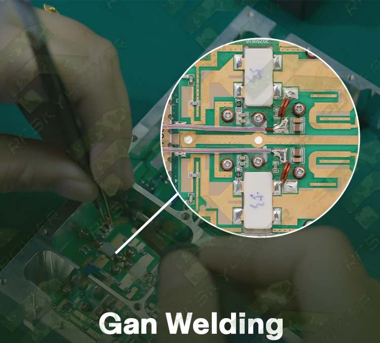
3rd Gen GaN Technology
Utilizing the latest High Power RF Gallium Nitride (GaN) transistors to deliver exceptional power density, wider bandwidths, and supreme efficiency across all bands.
Fail-Safe Protection
Every module integrates a robust 4-tier protection circuit covering Over-Temperature (80℃ shutdown), VSWR mismatch (Open/Short), Over-Voltage, and Over-Current.

MIL-STD-810F Rated
Engineered for brutal tactical environments. Operates reliably from -40℃ to +60℃ and passes rigorous military standards for vibration, shock, and altitude.
Need specific integration support or custom protocol development?
Contact Systems EngineeringFrom Concept to Deployment: 4-Week Sprint
Our streamlined development process delivered field-ready modules in record time without compromising quality or performance.

Requirements Lock
- Client technical review sessions
- Frequency allocation mapping
- Interface specification freeze
- Thermal envelope analysis

Rapid Prototyping
- Schematic design completion
- PCB layout optimization
- Component procurement (parallel)
- Simulation validation
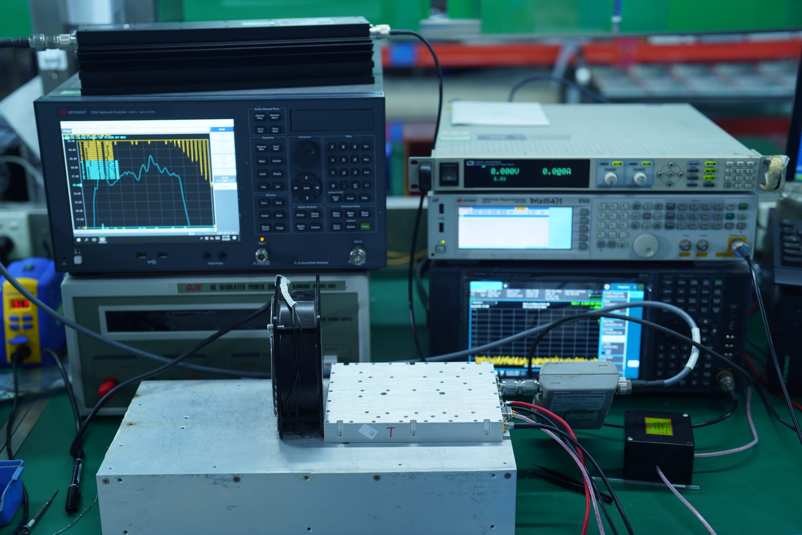
Build & Validate
- Prototype assembly
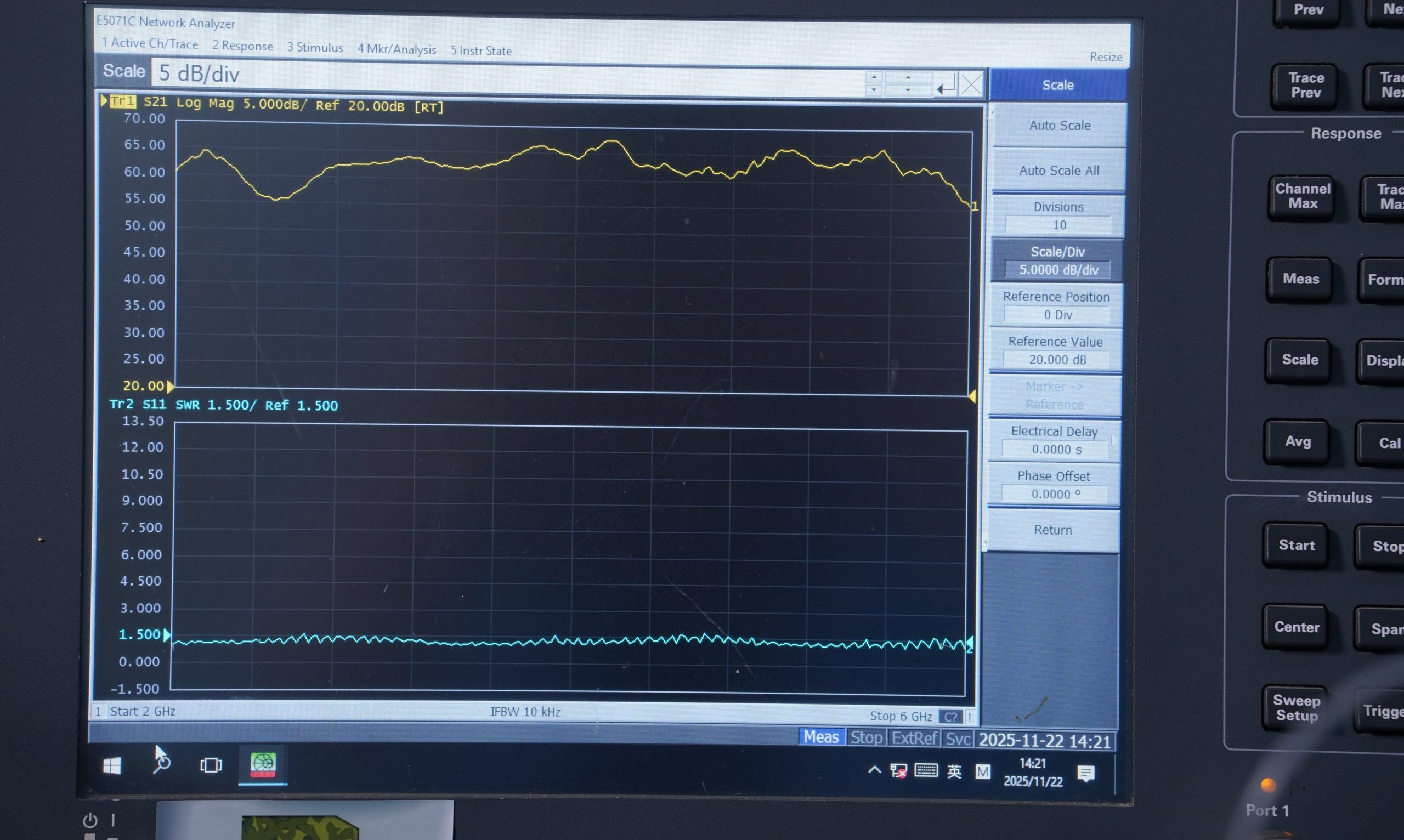
- RF performance verification
- Environmental stress screening
- Client witness testing

Batch & Ship
- Production run (50 units)
- 100% RF burn-in testing
- Documentation package
- Secure logistics delivery
Urgent deployment timeline? We specialize in accelerated development cycles.
Discuss Your Timeline RequirementsMeasurable Impact: Field-Proven Performance
Quantified results from live deployment demonstrate exceptional system performance exceeding all contract specifications.

Jamming Effectiveness
Successful neutralization rate across all targeted drone platforms in operational testing.
Effective Range
Maximum operational distance for reliable C2 link disruption against commercial UAVs.
Operational Uptime
Continuous operation capability with zero unplanned maintenance events over 90-day deployment.
Before vs. After Deployment
Traditional / Inferior Modules
- Poor Durability: Inferior thermal paste & no aging tests (>5% failure rate).
- Restricted Output: Technically limited to single-signal transmission only.
- Low Reliability: Lack of vibration and extreme environmental QC tests.
- Process Risks: Civil-grade parts and manual welding defects.
- Unstable Range: >5% gain error causing inaccurate distance control.
Our Hardened Solution
- Extreme Durability: GaN + Copper with 12-hour aging (<0.1% failure rate).
- Concurrent Output: Multi-signal synchronous transmission in complex scenarios.
- High Reliability: 6-fold rigorous environmental & vibration verification.
- Premium Process: CNC housing, 100% brand new parts & vacuum solder.
- Precise Range: <1% gain error for exact coverage and distance control.
Want to achieve similar results for your counter-UAS program?
Schedule Performance Review Call
"RF SKYPOWER transformed our counter-drone capability from a patchwork of components into a cohesive, battle-ready system. Their engineering team's deep understanding of real-world RF challenges—combined with their commitment to meeting our aggressive timeline—made them an invaluable partner. The modules have been performing flawlessly in the field for six months now."

Join our growing list of satisfied defense partners worldwide.
Become a Partner


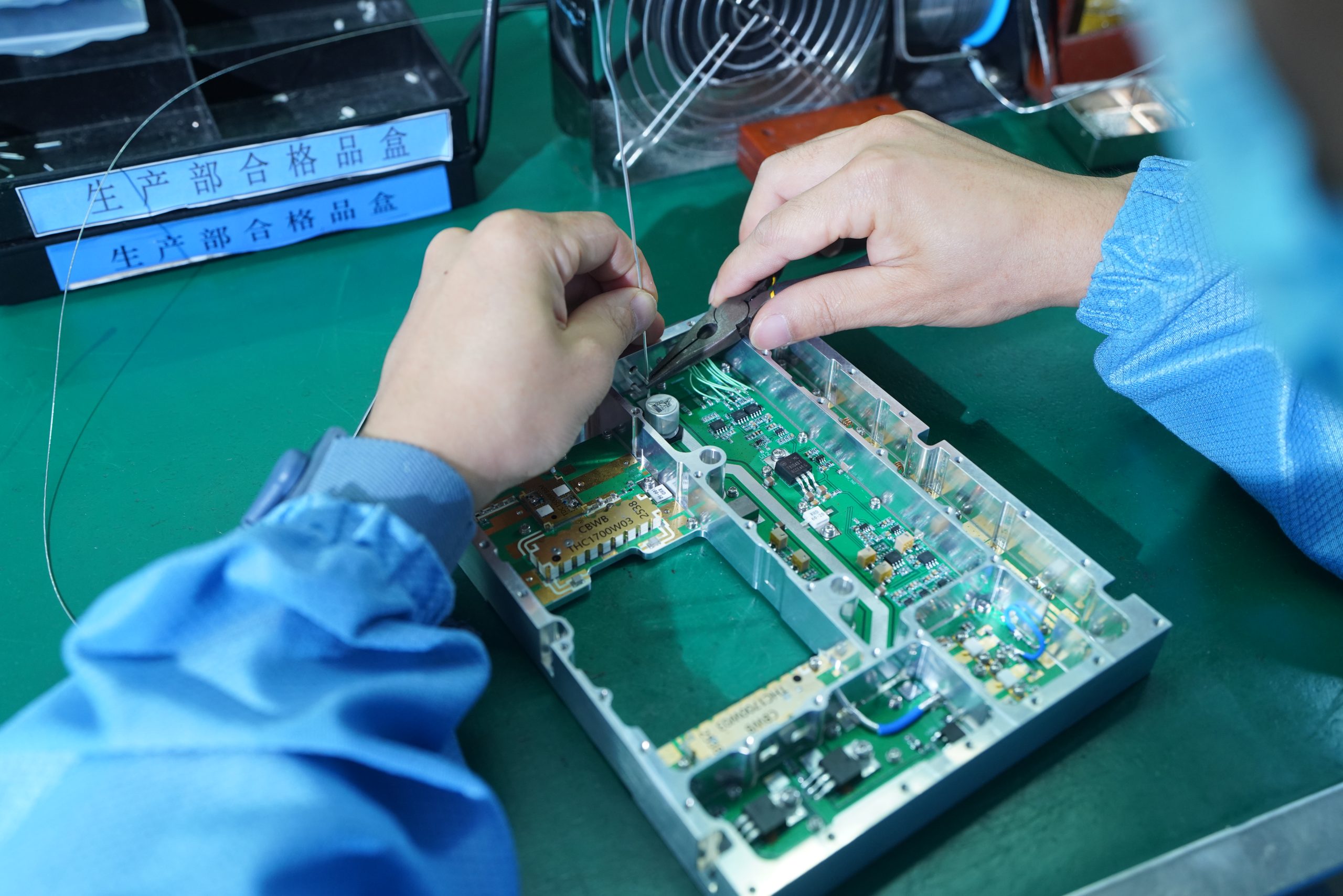
OUR METHODOLOGY
ENGINEERING EXCELLENCE BEHIND THE SOLUTION
From microscopic material audits to full-chain battlefield simulations, our proprietary 46-step process defines the precision limits of RF engineering. Excellence is not just about functionality; it's about absolute control over every micron-level detail.
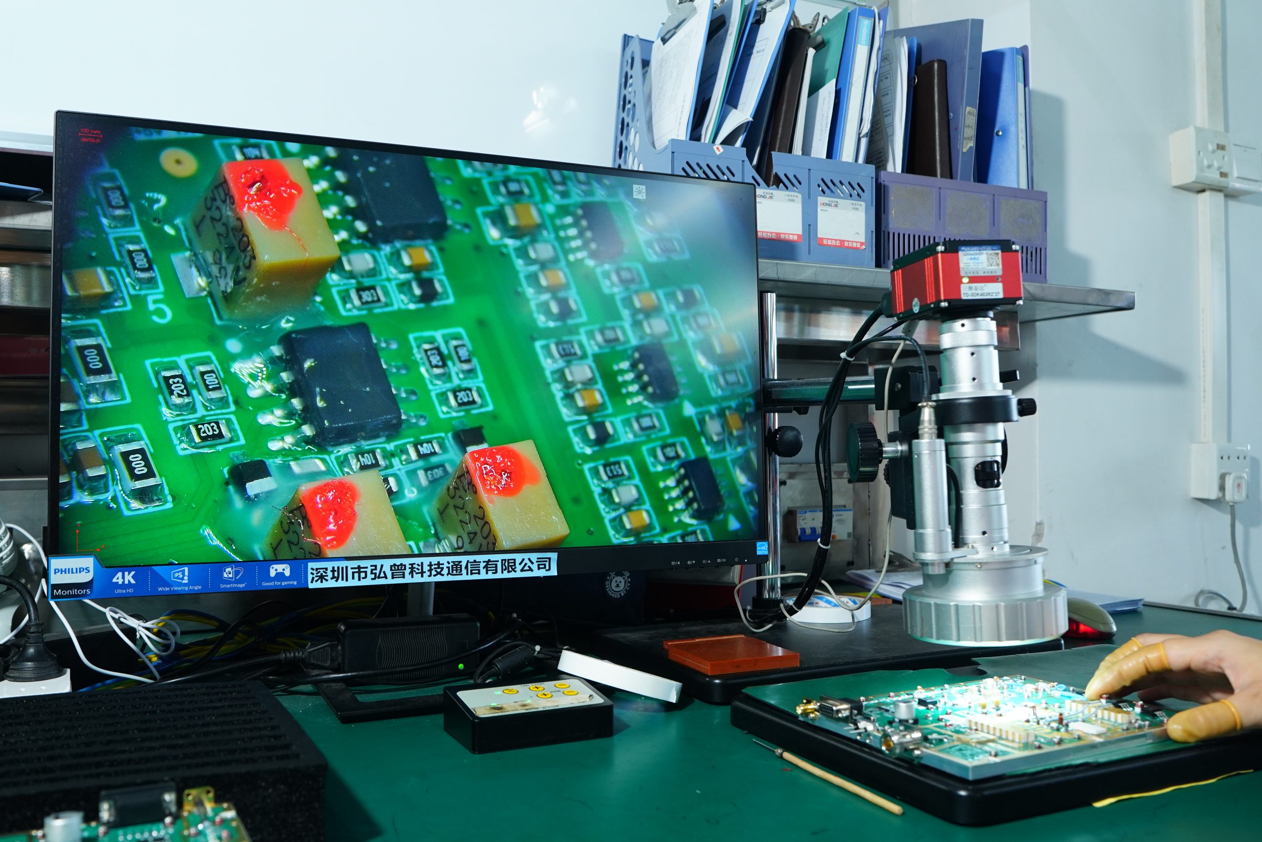
PCB Microscopic Material Inspection
Comprehensive inspection of pad flatness and solder mask under 500x magnification.

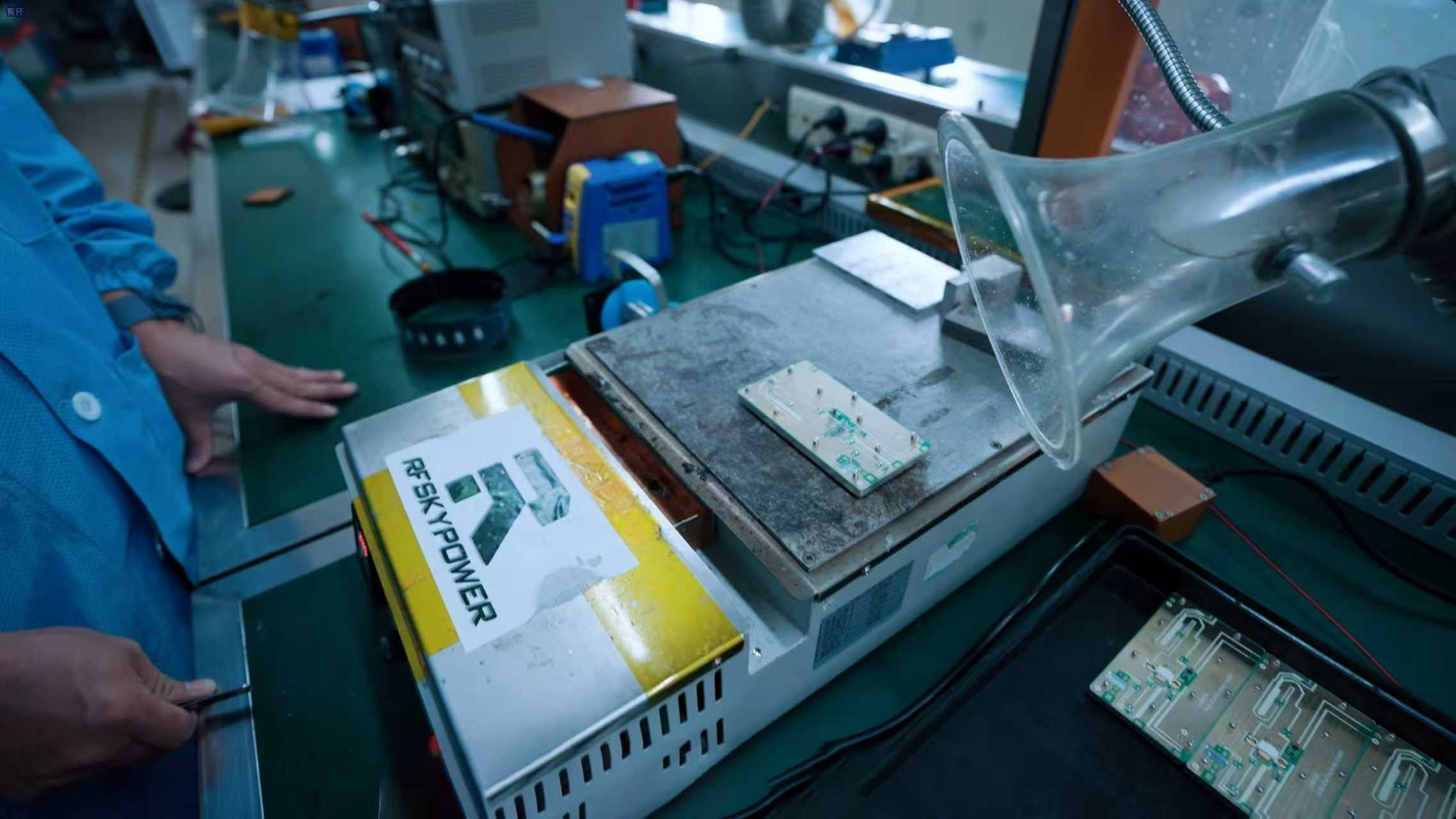
Power Tube Selection & Matching
Precise I-V curve sweep and gain matching for power transistors, consistency < 0.1dB.

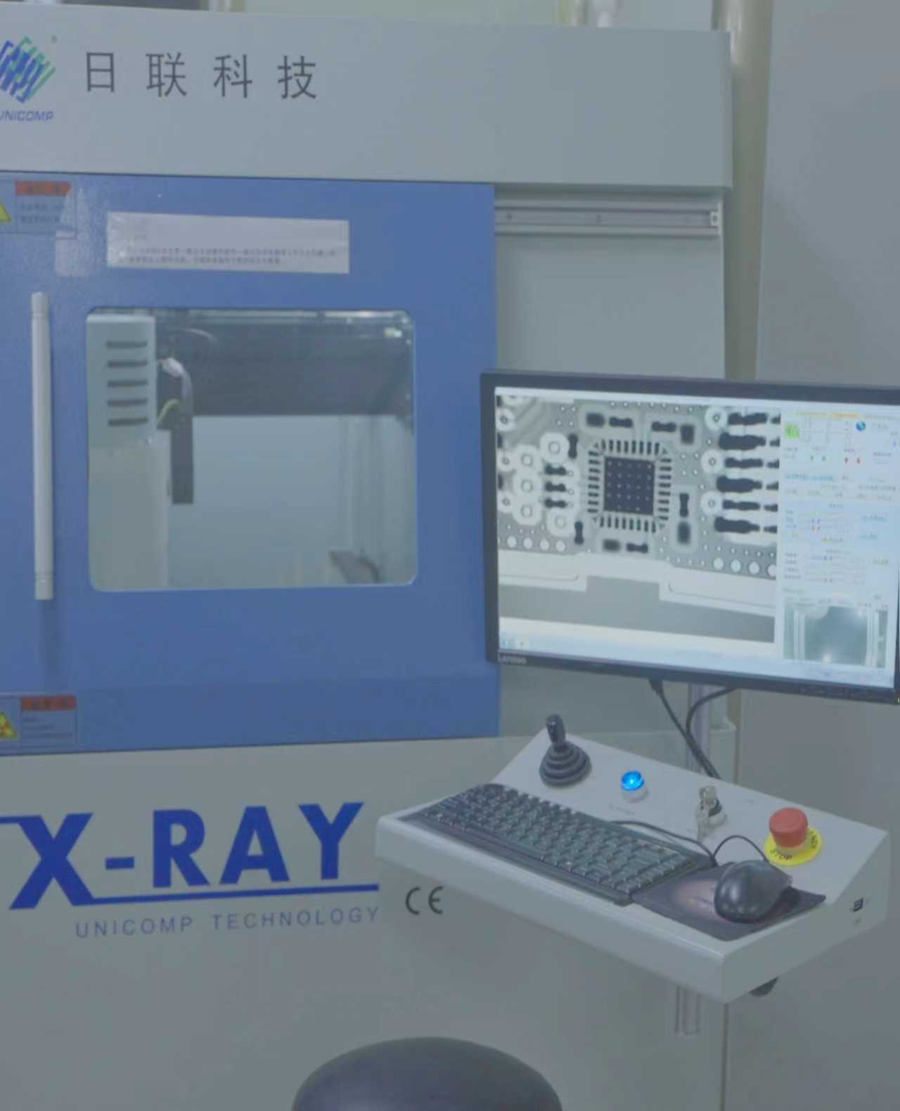
Core QC & X-Ray Analysis
Non-destructive evaluation of BGA/QFN solder joints; void rate must be < 2%.
Final Stage Sintering Process
Specialized vacuum sintering for high-power modules to ensure ultimate thermal transfer.
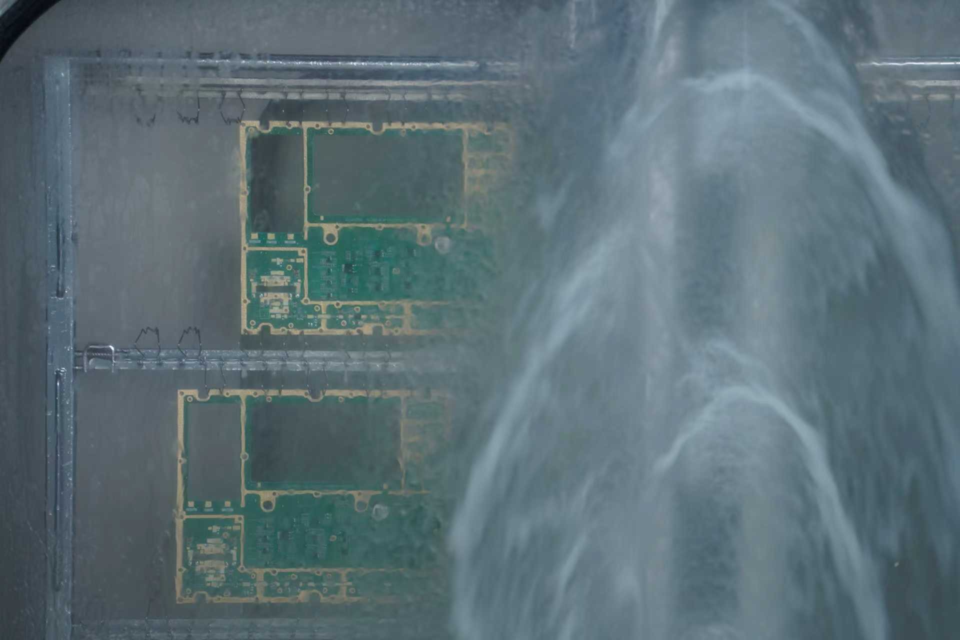
Deep Purification Cleaning
Thorough removal of flux residue and particles to prevent HF interference.
Full-Chain Precision Tuning
Comprehensive alignment of static current, RF signals, and safety logic.

Ultimate Surface Treatment
Final surface prep to ensure perfect adhesion of protective conformal coatings.

Extreme Reliability Verification
Battlefield simulation: vibration, 48h active burn-in, and thermal shock.
Key Insights & Lessons Learned
Every project teaches us something valuable. Here are the critical takeaways that shaped this success story.

"The biggest breakthrough came when we stopped treating thermal management as a post-design problem and integrated it from day one."— Lead RF Engineer, RF SKYPOWER
Wideband Matching Complexity
Achieving flat gain across 300:1 bandwidth ratio while maintaining stability proved exceptionally challenging with traditional matching networks.
Distributed Amplifier Topology
Implementing a traveling-wave amplifier architecture with optimized artificial transmission lines delivered the required bandwidth with excellent flatness.
Thermal Runaway Risk
High power density in compact form factor created localized hot spots exceeding GaN junction temperature limits during sustained operation.
Embedded Heat Pipe Array
Custom vapor chamber with micro-channel cooling reduced thermal resistance by 40%, enabling reliable continuous operation at full power.
Supply Chain Delays
Critical GaN transistors faced 16-week lead times that threatened the aggressive 4-week delivery schedule.
Strategic Inventory Buffer
Pre-positioned consignment stock with key semiconductor suppliers ensured immediate availability for urgent defense programs.
Frequently Asked Questions
Answers to the most common inquiries about this project and our C-UAS capabilities.

Our modular architecture supports coverage from 20 MHz to 20 GHz, or we can design optimized narrowband modules for specific threat frequencies. Common bands include 400MHz (telemetry), 900MHz, 1.2GHz, 2.4GHz (WiFi/FPV), and 5.8GHz. We also cover GNSS bands (L1/L2/L5) for navigation denial applications. Custom frequency configurations are available for specific operational requirements.
Standard development cycles range from 4-8 weeks depending on complexity. For urgent requirements, we offer expedited programs that can deliver prototype units in as little as 2 weeks. Our strategic component inventory and parallel processing capabilities enable these accelerated timelines without compromising quality. Production quantities typically ship 2-4 weeks after prototype approval.
All our defense-grade modules are designed and tested to MIL-STD-810H for environmental stress (temperature, humidity, vibration, shock) and MIL-STD-461G for EMI/EMC compliance. We can also provide testing to specific customer requirements or international equivalents (DEF-STAN, STANAG). IP67 ingress protection is standard for field-deployable units.
Absolutely. Our modules feature flexible interface options including SPI, RS-485, Ethernet, and analog control. We work closely with system integrators to ensure seamless compatibility with existing command-and-control architectures. We've successfully integrated with platforms from major defense primes and can provide custom interface adapters when needed.
We offer comprehensive lifecycle support including 24/7 technical hotline, field service engineers for deployment support, depot-level repair services, and long-term spare parts availability (10+ years). Extended warranty programs and preventive maintenance agreements are available. We also provide operator and maintainer training programs tailored to your team's needs.
RF SKYPOWER maintains rigorous export compliance programs covering ITAR, EAR, and international regulations. Our dedicated compliance team works with customers to navigate licensing requirements and ensure all necessary approvals are in place before shipment. We have established export authorizations with allied nations and can support government-to-government transfers.

Ready to Discuss Your RF Requirements?
Whether you're facing a complex counter-drone challenge, need high-power amplification for EW applications, or require custom RF modules for your defense platform—our engineering team is ready to deliver.
Request Information
Fill out the form and we'll respond within 24 hours.